ACCENT R's Screen Management Facility (SMF) is a package for manipulating windows (example: help and dialog boxes) independent of the physical terminal type. This package consists of system fields, system functions, statements, and commands which help design, compose, and keep track of window-based applications. SMF is used with video terminals, not hard copy devices or files.
Using SMF, images are composed how they appear on the screen. For example, ask the operator to enter data on one part of the screen, display the results on a second part of the screen, and display the processing status on a third part of the screen. The three components of the SMF are:
MENU DESIGN TOOL - allows the design of a wide variety of menus (simple or complex).
FORM DESIGN TOOL - allows the design of custom forms. Data can be entered and displayed according to the specification of the form.
WINDOW CONTROL TOOLS - are a set of system fields, system functions, statements, and commands that gives the power to create exactly the screen image wanted. This set of tools provides a comprehensive package for the development of window-oriented applications. The Window Control Tools also provide the foundation of the Menu Design Tool and the Form Design Tool.
SMF is one cohesive package, not three separate sets of tools. These tools can be used together. The Menu Design Tool can be used with the Form Design Tool. The Window Control Tools can be used as a stand-alone package or can enhance the Menu Design Tool and the Form Design Tool.
Applications using SMF can be developed with a combination of Process Modules (PM) and Command Modules (CM) or separately.
SMF writes to virtual windows instead of writing directly to the physical screen. There is no need to be concerned with the low-level character sequences required for manipulating the terminal screen. All terminal independent requests are converted into the proper sequence of codes needed to perform the action. If the terminal being used does not support the requested operation in hardware, the operation is emulated by software.
NOTES: SMF system functions may be used at the ACCENT R prompt (command level) to prototype screens. At command level, they require the SET command to be executed. They also require an integer system field to store the Window ID. @INTEGER (which is an array) can be used. User defined fields can not be used at command level. Users can not define fields "on-the-fly." Such fields must be predefined in a Process Module.
The Screen Management Facility (SMF) uses the concepts of the drawing board and windows, rather than the physical screen. A drawing board is a two-dimensional area on which windows are displayed and manipulated. This area is not limited to the size of the physical screen. A window is a rectangular part of the terminal screen on which ACCENT R reads and writes data using the Menu Design Tool, the Form Design Tool, and the Window Control Tools.
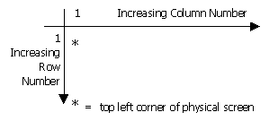
The drawing board is a logical structure for performing output operations on the terminal screen. The drawing board serves as a logical coordinate system in which the relative orientation of one or more windows is specified coordinate system.
Figure 1 illustrates the drawing board coordinate system. The position (1, 1) corresponds to the top left corner of the physical screen. The drawing board is a superset of the actual screen, therefore the number of rows and columns visible on the screen starts from this origin.
Figure 1 Drawing Board Coordinate System
When creating images to be placed on the screen, think in terms of windows rather than in terms of the physical screen. A window can contain almost anything; a data entry screen, help messages, reports, etc. This logical separation of the window from the physical screen allows the positions of windows to be easily changed. This change does not affect the reads and writes to that window. Using conventional programming techniques, an application that reads and writes the screen must be aware of the configuration of the entire screen.
When designing a window, the following must be defined:
- Number of rows and columns in the window
- Default rendition and window attributes of the window
- Contents of the window
RENDITION is a list of video attributes to be applied to the output of a window. Video attributes include bold, blink, reverse, and underline rendition video attributes.
WINDOW ATTRIBUTES window attributes are the characteristics that specify whether or not the window:
- Is surrounded by a border (which can be labeled)
- Echoes control characters like form-feed, vertical tab, etc.
- Shows a diamond-shaped icon when text wraps past the rightmost position in the window
WINDOW CONTENTS can be defined by any combination of Window Control Tools, Menu Design Tool, or Form Design Tool.
When a window is placed on the drawing board, it is said to be pasted. When the window is removed from the drawing board, it is said to be unpasted. Pasting a window specifies the drawing board coordinates at which the window origin is to be placed. (The window origin is its top left corner.)
The drawing board itself has no boundaries. A window can be pasted on the drawing board in such a way that some or all of the window does not appear on the terminal screen. A window is invisible unless it is pasted on the drawing board within the scope of the screen.
Multiple windows can be displayed at the same time. For example, the top of the screen can have a menu, the middle of the screen a data entry area, and the bottom of the screen help information which changes while moving from one data item to the next.
Windows can overlap on the drawing board. This is done by pasting one window over another. For example, on a data entry window when entering a particular character, a help box could be displayed at the top of the screen.
Figures 2 and 3 illustrate the paste and unpaste operations. Pasting windows on the drawing board is a logical operation that transfers the contents of a window to a location on the screen. This is done by specifying the row and column of the drawing board that coincides with the origin of the window. As shown in Figure 2, pasting a 6-row window "A" on the drawing board rows 1 through 6 and pasting a second 6-row window "B" on the drawing board rows 7 through 12 places window "B" immediately below window "A" on the screen.
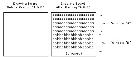
Figure 2 Paste Operation
A window can disappear from the physical screen by unpasting the window. If window "B" is unpasted, the results appear as in Figure 3.
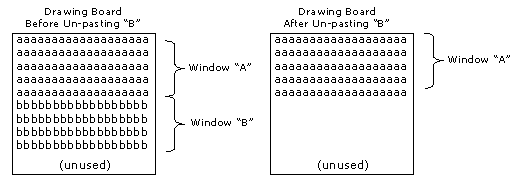
Figure 3 Un-Paste Operation
Un-pasting a window does not destroy the window or its contents. It simply removes the window from the drawing board, and thus from the screen.
Windows can overlap partially or completely, depending on the position and order in which they are pasted. Unpasting the top window causes the underlying windows to become visible. The unpasted window can be repasted to make it appear again.
Windows can be moved to a new location on the drawing board. This prevents the screen from being left blank during an unpaste and paste operation. Repasting a window makes it the uppermost window. Figure 4 shows the effect of repasting the window "B" farther to the right. Notice that window "B" has been pulled out of its former pasting order and is now the uppermost window, hiding part of the former uppermost window "C".
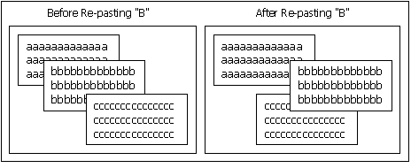
Figure 4 Re-paste Operation
A developer is defined as someone who builds window-driven applications with SMF. An end-user is defined as a person who runs the applications to process data.
![]()
![]()